- 您现在的位置:买卖IC网 > Sheet目录471 > MAX19700EVKIT (Maxim Integrated)EVAL KIT FOR MAX19700
�� �
�
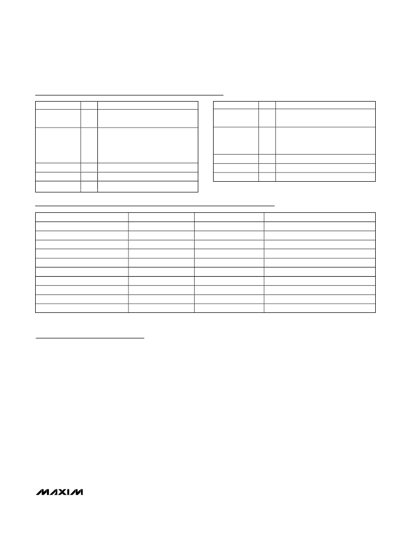
�MAX19700� Evaluation� Kit/Evaluation� System�
�Component� List� (continued)�
�DESIGNATION� QTY�
�DESCRIPTION�
�DESIGNATION� QTY�
�DESCRIPTION�
�U1�
�1�
�Maxim� MAX19700ETM� (48-pin� thin�
�QFN� 7mm� x� 7mm)�
�U7�
�1�
�Maxim� MAX3023EUD� (14-pin� TSSOP)�
�Maxim� MAX3027EUD� (14-pin� TSSOP)�
�20-bit� dual-supply� bus� transceiver�
�Dual-supply� 5-bit� signal� translator�
�U2�
�U3�
�U4,� U5�
�1�
�1�
�2�
�(56-pin� TSSOP)�
�Texas� Instruments�
�SN74AVCH20T245GR�
�Maxim� MAX9113ESA� (8-pin� SO)�
�Maxim� MAX4108ESA� (8-pin� SO)�
�U8�
�None�
�None�
�None�
�1�
�8�
�1�
�1�
�(14-pin� DQFN)�
�Fairchild� FXL5T244�
�Shunts�
�MAX19700� PC� board�
�MAX19700� EV� kit� software� (CD-ROM)�
�U6�
�1�
�Maxim� MAX4478AUD� (14-pin� TSSOP)�
�Component� Suppliers�
�SUPPLIER�
�AVX�
�Central� Semiconductor�
�Coilcraft�
�Diodes� Inc.�
�Fairchild�
�Panasonic�
�TDK�
�Texas� Instruments�
�Vishay/Vitramon�
�Zetex� USA�
�PHONE�
�843-946-0238�
�631-435-1110�
�847-639-6400�
�805-446-4800�
�888-522-5372�
�714-373-7366�
�847-803-6100�
�972-644-5580�
�203-268-6261�
�631-543-7100�
�FAX�
�843-626-3123�
�631-435-1824�
�847-639-1469�
�805-446-4850�
�—�
�714-737-7323�
�847-390-4405�
�214-480-7800�
�203-452-5670�
�631-864-7630�
�WEBSITE�
�www.avxcorp.com�
�www.centralsemi.com�
�www.coilcraft.com�
�www.diodes.com�
�www.fairchildsemi.com�
�www.panasonic.com�
�www.component.tdk.com�
�www.ti.com�
�www.vishay.com�
�www.zetex.com�
�Note:� Indicate� that� you� are� using� the� MAX19700� when� contacting� these� component� suppliers.�
�Quick� Start�
�Recommended� Equipment�
�?� DC� power� supplies:�
�Analog� (VDD)� +3.0V,� 100mA�
�?� Analog� bandpass� filters� (e.g.,� Allen� Avionics,� K&L�
�Microwave)� for� input� signals� and� clock� signal�
�?� Two� spectrum� analyzers� (e.g.,� HP� 8560E)�
�?� One� 10-bit� digital� pattern� generator� (e.g.,� Tektronix�
�DG2020A)�
�Clock� (CVDD)�
�Digital� (OVDD)�
�Buffers� (BVCC)�
�+3.0V,� 100mA�
�+1.8V,� 100mA�
�+3.3V,� 100mA�
�Procedure�
�The� MAX19700� EV� kit� is� a� fully� assembled� and� tested�
�surface-mount� board.� Follow� the� steps� below� to� verify�
�Op-Amp� Positive� (VOP)� +5.0V,� 250mA�
�Op-Amp� Negative� (VON)� -5.0V,� 250mA�
�?� Signal� generator� with� low� phase� noise� and� low� jitter�
�for� clock� input� signal� (e.g.,� HP� 8662A,� HP� 8644B)�
�?� Two� signal� generators� with� low� phase� noise� for� ana-�
�log� signal� inputs� (e.g.,� HP� 8662A,� HP� 8644B)�
�?� Logic� analyzer� or� data-acquisition� system� (e.g.,� HP�
�16500C,� TLA621)�
�board� operation.� Do� not� turn� on� power� supplies� or�
�enable� signal/data� generators� until� all� connections�
�are� completed.�
�Command� Module� Setup�
�1)� Set� both� switches� at� SW1� to� the� OFF� position� to� dis-�
�able� the� SDA/SCL� pullup� resistors.�
�2)� Place� a� shunt� across� pins� 1-2� of� the� VDD� select�
�jumper� (command� module� working� voltage� set�
�to� +3.3V).�
�_______________________________________________________________________________________�
�3�
�发布紧急采购,3分钟左右您将得到回复。
相关PDF资料
MAX19985AETX+T
IC MIXER DOWNCONV 36-TQFN-EP
MAX19993ETX+
IC MIXER DOWNCONV 36TQFN
MAX19994AEVKIT#
KIT EVAL FOR MAX19994A MIXER
MAX19995ETX+T
IC DOWNCONVERTER 2CH 36TQFN
MAX19995EVKIT#
EVALUATION KIT FOR MAX19995
MAX19996AEVKIT#
EVALUATION KIT FOR MAX19996A
MAX19996ETP+T
IC MIXER DOWNCONV 20-TQFN-EP
MAX19997AETX+T
IC DOWNCONVERTER 2CH 36TQFN
相关代理商/技术参数
MAX19705ETM
功能描述:ADC / DAC多通道 RoHS:否 制造商:Texas Instruments 转换速率: 分辨率:8 bit 接口类型:SPI 电压参考: 电源电压-最大:3.6 V 电源电压-最小:2 V 最大工作温度:+ 85 C 安装风格:SMD/SMT 封装 / 箱体:VQFN-40
MAX19705ETM+
功能描述:ADC / DAC多通道 7.5Msps CODEC/AFE 1.8/2.7-3.3V RoHS:否 制造商:Texas Instruments 转换速率: 分辨率:8 bit 接口类型:SPI 电压参考: 电源电压-最大:3.6 V 电源电压-最小:2 V 最大工作温度:+ 85 C 安装风格:SMD/SMT 封装 / 箱体:VQFN-40
MAX19705ETM+GH7
功能描述:ADC / DAC多通道 10-Bit 7.5Msps Ultra-Low-Power Analog Front-End RoHS:否 制造商:Texas Instruments 转换速率: 分辨率:8 bit 接口类型:SPI 电压参考: 电源电压-最大:3.6 V 电源电压-最小:2 V 最大工作温度:+ 85 C 安装风格:SMD/SMT 封装 / 箱体:VQFN-40
MAX19705ETM+T
功能描述:ADC / DAC多通道 7.5Msps CODEC/AFE 1.8/2.7-3.3V RoHS:否 制造商:Texas Instruments 转换速率: 分辨率:8 bit 接口类型:SPI 电压参考: 电源电压-最大:3.6 V 电源电压-最小:2 V 最大工作温度:+ 85 C 安装风格:SMD/SMT 封装 / 箱体:VQFN-40
MAX19705ETM+TGH7
功能描述:ADC / DAC多通道 10-bit 7.5Msps Ultra-Low-Power Analog Front-End RoHS:否 制造商:Texas Instruments 转换速率: 分辨率:8 bit 接口类型:SPI 电压参考: 电源电压-最大:3.6 V 电源电压-最小:2 V 最大工作温度:+ 85 C 安装风格:SMD/SMT 封装 / 箱体:VQFN-40
MAX19705ETM-T
功能描述:ADC / DAC多通道 RoHS:否 制造商:Texas Instruments 转换速率: 分辨率:8 bit 接口类型:SPI 电压参考: 电源电压-最大:3.6 V 电源电压-最小:2 V 最大工作温度:+ 85 C 安装风格:SMD/SMT 封装 / 箱体:VQFN-40
MAX19705EVCMOD2
功能描述:ADC / DAC多通道 Evaluation System for the MAX19705 RoHS:否 制造商:Texas Instruments 转换速率: 分辨率:8 bit 接口类型:SPI 电压参考: 电源电压-最大:3.6 V 电源电压-最小:2 V 最大工作温度:+ 85 C 安装风格:SMD/SMT 封装 / 箱体:VQFN-40
MAX19705EVCMODU
功能描述:ADC / DAC多通道 Evaluation System for the MAX19705 RoHS:否 制造商:Texas Instruments 转换速率: 分辨率:8 bit 接口类型:SPI 电压参考: 电源电压-最大:3.6 V 电源电压-最小:2 V 最大工作温度:+ 85 C 安装风格:SMD/SMT 封装 / 箱体:VQFN-40